Introduction
Clock recovery is the process of extracting timing information from a data stream to allow the receiver to decode the transmitted data. In ethernet communication, digital data is sent without the clock signal and therefore must be regenerated at the receiver, using the timing information from the data stream.
Higher data rate transceivers are equipped with Clock Data Recovery (CDR) to ensure the transmitted and received signals are synchronized for optimal transmission. In this article, we will discuss situations when CDR has to be bypassed in transceivers and how you can control CDR values in MSA registers.
Tx/Rx CDR Control in Transceiver
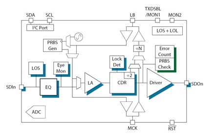
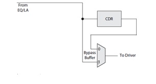
CDR is also referred to as a re-timer for the re-generated clock and is where LOL (loss of lock) and jitter regeneration occurs. The block diagram below shows the CDR location.
There may be a few instances where CDR has to be bypassed. For example, in some applications running transceivers at specific bit rates may not be supported because the clock does not lock. So, you can bypass the CDR to mitigate jitter generation.
Also, shutting down CDR saves power. This is because typically four CDRs are used for module configuration, but that energy can be conserved if you do not need to use CDR jitter mitigation.
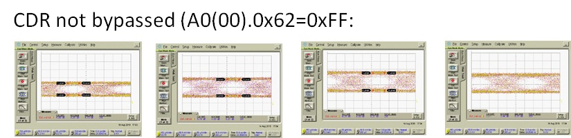
Tx/ Rx CDR Control (100G-LR4 H4A2016085 at 10.3Gbps)
In this example, we are running a 100G module with 4 lanes of 25G. Here, we changed the PHY to run at 10.3Gbps, instead of the usual 25Gbps. Most PHYs can do that, but when you run it, you get jitter like in the image above because the clock is not being regenerated (CDR not bypassed). The clock is supposed to lock on 25Gb/s, but now that the data rate is 10.3Gb/s, the clock tries to regenerate and leaves large jitters.
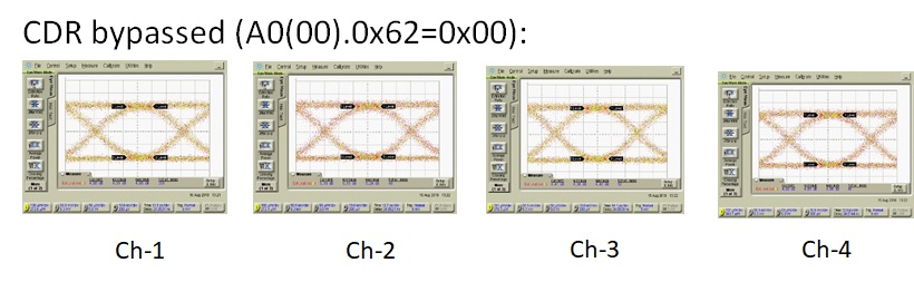
For the CDR bypassed graphic, we have the same signal. In this case, we changed the CDR to bypass mode, which is allowed in MSA. The signal is very clean even if you run it at 10.3 Gbps.
Key Takeaways
To bypass the CDR , there are two things to be checked: whether the CDR bypass function is supported in the transceiver and then change the 62 hex register to 00. Immediately, you can see the loss of lock. FF on A0.05, indicates transmitter, receiver CDR loss of lock (LOL), are all set.
A0(00).0x62 = 0x00 for Tx-CDR 4/3/2/1 & Rx-CDR 4/3/2/1 CDR all off
= 0xFF for CDR all on
If you would like to know learn more about any of the topics discussed above, contact us.
