APDs or Avalanche Photo Diodes are the most commonly used photo detectors in optical transceivers. To learn more about APD fundamentals and why they are used in optical transceivers, read this article.
In this article, we explain APD damage, its causes and proper operation techniques to avoid APD failure.
APD failure
The most frequent cause of failure of ER and ZR transceivers is APD damage.
APD damage can occur when the maximum input power of the receiver (specified on the manufacturer datasheet) is not observed. This operating parameter, specified as the “damage threshold” is from about -3dBm to -7dBm. When input power of the receiver exceeds the threshold, APD failure may happen. The most likely scenario for this type of failure is when the user connects the transmitter directly to the receiver with a short fiber, back-to-back. When this happens, the absorption layer in the APD is damaged. This leads to a short in the circuit ground which affects the maximum current flow.
Replacing an APD based transceiver can be expensive:
For example, the cost of a 100G ER transceiver is about 4 times that of an LR and a 100G ZR is almost 10 times LR!
APD Failure – An Example
We will go through an example to demonstrate how we can identify and troubleshoot APD damage in a standard QA environment.
Here, we have two serial numbers, which were returned from a customer and have gone through the QA test.
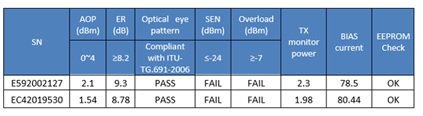
Tests also show that the RxPwr DDM is always -3.74dBm regardless the levels of power.
If you look at the above table, all looks good on the transmitter side, but it’s a different situation on the receiver side: sensitivity, overload, and DDMI on receiver power input all fail. These three parameters combined can tell us for certain that the APD is damaged.
Troubleshooting
The next step of this process is the actual trouble shooting. First, we measure the pass voltage at the cathode of the APD. If Vapd is very low, ( normal standard is 30V) it’s an indicator that something is wrong. Then we measure the resistance from APD cathode to electrical GND. If that is very low, where the standard is in the range of mega ohms (MΩ), it is again a sign that there is an issue. Lastly, we replace the APD ROSA to confirm APD failure; if the ROSA works again, then it is a sign that the previous ROSA on the PCB was damaged.
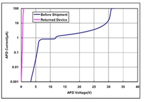
The blue line on this graph (V-I test) represents the current to voltage curve on a normal transceiver. The pink line represents the same test on the failed module; you can see that the current begins to drain a lot more even at minimal bias, which is a very typical APD damage characteristic.
We took it a step further and de-lidded the APD ROSA to inspect the APD chip. If you look carefully, there are two scratches on the surface, which is a sign that the chip has been damaged due to excess optical power.
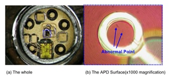
Lastly, on the cross-sectional view, you can see the damage in the absorption layer, which is close to the multiplication region “M”.
How can you prevent APD damage?
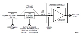
1.Add APD current protection circuitry – The power supply circuit with current monitor protects the APD dynamically while providing the bias voltage. The current monitor is very important and must be very fast. When light strikes the chip, the current needs to be shut off immediately without any glitches or delays, or the chip will be damaged.
2. Robust APD chip design – Recent papers show that the new approach in chip design has increased the damage threshold to +4dBm. However, note that transmitter powerof a 100G ER transceiver can be as high as +6dBm/ ch. Again, by connecting transmitter and receiver back-to-back, you can damage the APD. Sometimes the damage can be latent, meaning it will not happen immediately, but later, which could be even more dangerous.
3.Lastly, when you deal with APD receivers, always use a 10dB in-line optical attenuator in front of the ROSA. This is the most inexpensive and reliable solution.
For an end user, a key takeaway is to not connect ER or ZR transceivers back-to back (transmitter to receiver) with a short fiber. Considerable design experience goes into developing robust transceiver modules. If you encounter a high failure rate, it is possible that the design itself is lacking and it may be time to switch to another manufacturer. Contact us if you have any questions on long distance optical transceivers.
Related Products
