Transceiver testing is an important step in the quality control process that’s critical for engineers. Test reports are included – or should be – with every transceiver module sent by quality fiber optic vendors. But interpreting them requires skill.
Craig Polk, engineer and Vitex product manager, walks us through how to read a sample transceiver quality assurance test, calling out key engineering performance parameters that affect optical transceiver quality. He also provided useful tips and best practices on interpreting test results.
We have included a sample QA test report as a reference to make this easier to follow.
Q: What quality assurance tests are done for transceivers? Are they done for each module?
A: All transceivers are tested as part of the quality control process. First, a visual inspection is performed to check for physical defects, as well as cosmetic or labeling problems, make and model numbers, certifications, country of origin, etc.
Our sample test report (Figure A) measures transceiver transmit characteristics by key performance parameters:
- optical output power;
- extinction ratio.
Receiver reliability test results include optical sensitivity, maximum input power and signal detection. Maximum input power tests allow manufacturers to validate transceiver power consumption. Signal alarms are typically tested to check for signal loss.
Some manufacturers also measure wavelengths.
What customers do on their end varies. They typically verify the transceiver is going to work and want to reproduce the results provided to them in these test reports.
Q: Are there any false reports or is there any problem with unreliable tests or data?
A: Multiple tests are done multiple times to ensure consistency and reliability of data.
Q: Are different tests done in different industries?
A: Quality assurance tests are standardized and used across industries. But based on the specific industry application, the customer may require additional tests.
Q: Can you simplify the parameters on the sample test report and explain how to read it.
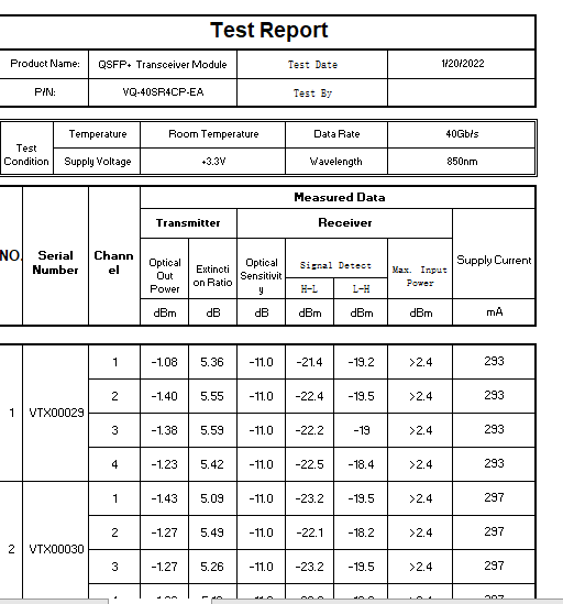
At the top of the report, the manufacturer identifies the type of transceiver being tested – by form factor, testing date, and test conditions.
The second row specifies Test Conditions: i.e., Temperature, Data Rate, Supply Voltage, and Wavelength (nm = nanometer).
Scrolling down, the very next section of the report provides Measured Data and is organized in several columns from left to right, distinguishing each transceiver tested. Each transceiver tested is identified by number and also corresponds to a specific serial number as indicated on the top of that column (first two columns from the left, i.e., VTX00029 is the serial number provided for the first transceiver tested). The transmitter column (fourth and fifth from the left) defines what’s being tested (i.e., optical out power, extinction ratio).
- Optical Out Power, also termed output optical power, measures the average output power of the transmitter under normal operating conditions. It’s an important parameter which directly affects the communication quality of the transceiver.
- Extinction Ratio: The extinction ratio is the ratio of the energy (power) used to transmit a logic level ‘1’, to the energy used to transmit a logic level ‘0’. An eye-diagram is commonly used.
- Receivers are tested for the following criteria: (columns six, seven, eight): optical sensitivity, signal detection, and maximum input power, as quantified in terms of dBm or db. dB stands for decibel (dB) a relative scale representing the power and voltage strengths of electronic equipment. Because the decibel is logarithmic and therefore a dimensionless unit, the unit dBm (decibel-milliwatts), is used as an absolute point of reference. The last column on the right measures supply current (electrical) in mA or milliamps.
- Receiver optical sensitivity is a key parameter in measuring the performance of optical transceiver receiving devices. This test runs the power attenuation of the signal through a programmable optical attenuator, which enables the optical transceiver receiving signals of different power to be completed by comparing the error rate of different optical power by the error meter. The better the receiver sensitivity, the smaller the minimum receiving light power (which translates to a lower number). Conversely, if the reception sensitivity is poor, the higher the requirements are for the optical receiver device (which translates to a higher number);
- Signal Detection defines at what point there’s a warning (an alarm) that the signal is getting too low to ensure that there’s no signal loss;
- Maximum Input Power: An engineering spec defines the level at which that component can receive a signal without damaging the receiver.
Each transceiver (as identified by serial number) is tested four times (indicated in this report on lines 1, 2, 3, 4). While there’s no pass/fail specified on this sample report, all results are passing scores and fall within the IEEE or MSA standards. Customers may request IEEE or MSA requirements to be included in test reports.
Vitex, based in northern New Jersey, has been supplying fiber optics products and solutions to customers in multiple industries for more than two decades. Our highly trained staff includes engineers with deep fiber optics knowledge who can customize solutions to your needs and provide US-based technical support. For more information, visit our website or contact info@vitextech.com.
Related Products
