Latency is an important consideration in designing optical networks. It becomes even more critical in certain applications like super computing, gaming and financial technology.
What is latency?
Simply put, latency is the time it takes for a signal to travel from point A to point B. Many components contribute to latency in an optical network –fiber and optical components are the chief among them. For optical transceivers, latency is measured from the transmitter input to the receiver output.
Is transceiver latency important?
Transceiver latency is a key spec in enterprise fiber optic networks especially in financial institutions. It is the one of the few variables that can be optimized since fiber path delay is fixed.
Speed of light
The speed of light in free space is about 3e8 m/s, which means that when light travels 1km, there is a latency or time delay of 3.34 microseconds (µs).
Light traveling through optical fiber moves more slowly than in free space. For a single mode optical fiber with a refractive index of 1.4682, latency is about 5 nanoseconds per meter, or 4.9 microseconds per kilometer.
Typical Latency for a 10G Transceiver
Latency for a 10G transceiver is usually 3ns.
| Parameter | Maximum | Unit | Remarks |
|---|---|---|---|
| Latency | 3 | ns | Electrical data in to electrical data out of the test-board using optical loopback between Tx and Rx, applicable for the complete Sensitivity and Temperature range. |
How To Measure Latency
One method is to use calibration to subtract out system delays as explained below:
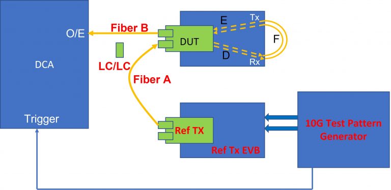
Test Setup
- Test Pattern Generator = Xilinx IBERT
- Ref Tx EVB
- DUT in EVB
- RF Cables (48”)
- Fiber Optic Cables
- LC-LC Adapter
- DCA 86100C + 86105C
- Fiber A and Fiber B to be calibrated out
To Calculate Latency
- To measure the total delay, you start by making two calculations. First, you would have to calculate all together (A) = 10G Test Pattern Generator + RF Cables + EVB + Ref Tx + Fiber A + DUT-Rx + RF Trace D + FR Cables F + RF Trace E + DUT-Tx + Fiber B.
- Secondly, you take the calculations without the DUT (B)= 10G Test Pattern Generator + RF Cables + EVB + Ref Tx + Fiber A + Fiber B.
- In this example, (A) – (B) = 6.707 ns. Note that this difference also includes the RF traces and loopback cables.
- Measure the RF traces delay: Traces (Rogers RO4003C Er~3) D and E (4.720″) = 0.752
- Measure the RF cables delay: RF Cables F (48″) = 5.171 ns
- Calculate DUT latency by subtracting your values = 6.707ns – 5.171ns =0.782ns
Vitex now offers ultra-low latency AOCs and transceivers based on CDR architecture. Contact us at sales@vitextech.com to learn more about our cutting edge DSP-free products.
Related Products