Transceivers are vital components of an optical network and low- quality ones have adverse impact on network performance. Testing of fiber optic transceivers is necessary to ensure that they comply with industry specifications. The eye diagram is a common method used to analyze high-speed digital signals.
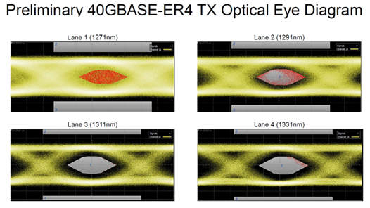
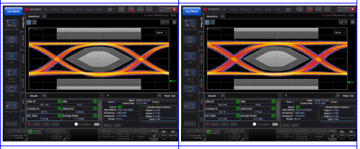
A large telecom customer approached us when they faced issues with testing a 40G ER4 transceiver in their lab. They were concerned when their test data did not produce satisfactory results. Figures 1 and 2 depict their test set up and eye diagram.
Key Parameters for Test
- Signal to be tested: 4×10.3Gbps NRZ at PRBS9
- Tx eye diagram per IEEE802.3ba

Our FAE immediately noticed a couple of things that stood out in the test set up.
1.In any Tx O/E conversion, the optical power into the CDR/OE plug-in needs to be as high as possible so as not to let any noise level from the detector to degrade the eye. The customer’s set up included a 10dB attenuator, a demux module (~2dB) and a 3dB coupler internal to the N1078A (4dB). The total insertion loss from the DUT (Device Under Test) to the 86105C O/E plug in is 10+2+4=16dB!
Optical attenuators are typically used to lower the power signal when testing receivers. In this case, the attenuator was lowering the power too much. The power should be high to overcome the noise inside the CDR. Otherwise, the Tx eye could include the noise from the Rx.
The Demux module was also adding an insertion loss of 2 to 3B to the set up. The ideal test method would be to avoid using a demux module and disable the three lanes. This requires some working knowledge of the transceiver and may not be very practical to an end user.
The 3dB internal power coupler contributes about 4-5dB.
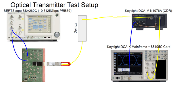
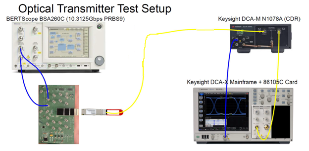
The other issue is the lack of buffer IC on the evaluation board (EVB). When you connect a pattern generator to an EVB with high speed RF cables, the best practice is to buffer the differential signal with a CDR IC on board to re-clock the signal before sending it to the DUT in order to eliminate the unnecessary delay and reflection. Again, the rule of thumb is to make sure there is no degradation from the test set adding to the DUT.
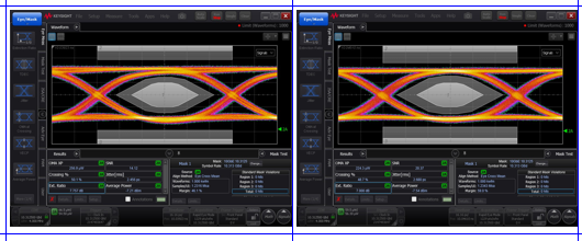
As digital signals become ever faster, eye diagrams provide the means to quickly and accurately measure signal quality and system performance. Ensuring that there is no degradation from the test set at every step goes a long way in getting best test results.
If you need further information on optical transceiver testing, contact us at info@vitextech.com.
Related Products
