Adoption of high data rate transceivers like 400G have led to changes in the way optical modules are tested. Standards bodies like IEEE have defined measurement metrics to quantify the performance of an optical transceiver and ensure inter-operability.
Transceiver Transmitter Testing
Traditional Mask and Transmitter & Dispersion Penalty (TDP) tests used for NRZ (non-return-to zero, PAM2) signals were extremely useful for low-speed signals. The disadvantage of TDP measurements were that they were slow and required expensive test equipment. As a result, TDEC (Transmitter and Dispersion Eye Closure) test evolved to replace the TDP test. TDP and TDEC tests both compare the transmitter under test to an ideal or golden transmitter. While the TDP uses an actual reference transmitter, the ideal signal in TDEC is simulated. TDEC gives a measure of eye-shape and includes the effects of Inter-Symbol Interference jitter (results in modal dispersion) caused due to system impairments. TDEC provides a direct correlation with BER. Thus, for different BER values, you can measure the amount of TDEC penalty allowed in the system.
TDEC to TDECQ
With data rates increasing, the industry shifted from NRZ to PAM4 modulation. PAM4 has the advantage of packing 2 bits into a symbol, reducing the bandwidth by half.
In PAM4 signaling, TDEC was replaced by TDECQ which stands for “Transmitter and Dispersion Eye Closure Quaternary” and is a key optical measurement for equalized optical links. TDECQ is a type of penalty and is used to measure the performance of a transmitter under test. It calculates the degradation (noise, ISI, modal dispersion) that a receiver can add to a transmitter signal and measures the Vertical Eye Closure parameters.
Test Set Up
The test set up for measuring TDECQ is the same as that for TDEC except that it includes a 4th order Bessel-Thompson filter (sampling oscilloscope) and a reference equalizer. The setup used for measuring TDECQ is shown below:
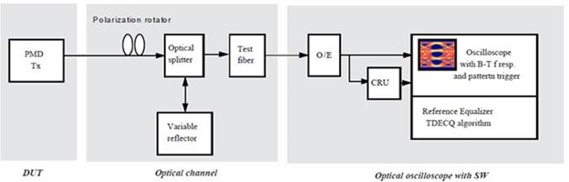
The noise generated by the O/E converter and Oscilloscope introduces ISI and modal dispersion to replicate worst-case conditions. A resultant waveform after passing through this oscilloscope has completely closed eyes. The equalizer becomes a mandatory addition to this setup to “open-up the eyes” of the waveform.
TDECQ Calculation
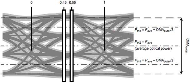
To compute TDECQ, 8 vertical histograms (4 above and 4 below the avg. power) at 0.45UI and 0.55UI are taken into consideration as shown below:
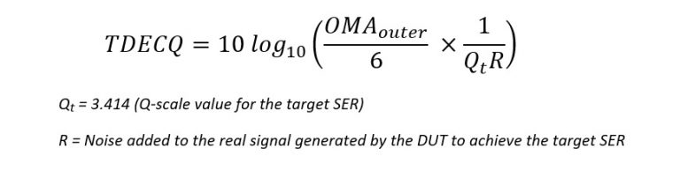
In the test, noise is added to the signal until the targeted SER (Symbol Error Ratio) is attained. This process is done to the DUT (Device Under Test) and the virtual ideal transmitter. The difference in noise levels represents the power penalty for the DUT.

For an ideal transmitter, TDECQ =1. The lower the TDECQ value, the better the performance of the transmitter. TDECQ cannot be lower than 1 since the amount of noise added to the ideal transmitter would always be larger than that added to the DUT.
IEEE defines multiple limits for TDECQ depending on the application (eg. DR, FR, LR etc.). For example, for 400GBASE-DR transmit characteristics, the limit is 3.4 dB.
Conclusion
TDECQ is a measurement metric that will become more mainstream as transceivers continue to adopt PAM4 modulation. It provides a convenient and more accurate testing method relative to traditional TDP tests.
Contact us if you have any questions about optical transceivers and their testing.
Related Products
